
see X31-61 caliper restoring
Part 1. About the brake system
Where do the brakes start?
"With the pedal" - some will say. Indeed, for the driver, it is the pedal that is the point of contact with this vital system.
"With the tread" - others will say, and they will also be right. There will be no grip in the contact patch "tire-road", and there will be no braking.
But these are the extreme, "end points" of the system. In reality, of course, the reliability of deceleration is associated with the serviceability of each component of the brake system.
If we simply list them, then for our cars with a hydraulic system we get the following:
- Brake pedal
- Master brake cylinder
- Vacuum booster
- Reservoir with fluid reserve
- Pipelines and hoses
- Distributors
- Calipers with working cylinders and pads
- Pads/Shoes
- Brake discs
- Brake fluid
- Parkbrake: lever, adjustable cable, brackets, pads/shoes with a spreading mechanism, drum.
In addition to the above, I would also include some electrical components in the brake system: the switch above the pedal, brake light bulbs, fluid level sensor in the reservoir, pressure sensor in the system, handbrake switch, control lamp in the instrument panel, pad thickness sensors and the wiring connecting all of this.
If we approach it from a slightly different angle and analyze which component of the system is exposed to the greatest destructive atmospheric influences, then the brake calipers will undoubtedly be the leaders. Combining a significant number of interconnected parts that must move smoothly and without jamming, this unit, nevertheless, heats up to high temperatures during operation, is doused with water when driving through puddles, experiences high loads on displacement and rupture, must work stably for a long time, and at the same time consists of dozens of parts, most of which are subject to corrosion!
In my case, the front and rear brake calipers at the time of removal were pretty rusty Sumitomo mechanisms, which still partially performed their functions (the car drove and braked before the work began, although I did both very carefully and only when necessary :)
Part 2. Disassembling
.jpg?1727450748565)

Dismantling and disassembly revealed almost universally penetrating corrosion, torn rubber boots, cracked homemade pads in some places, and also (thanks you for this, nameless Japanese engineer!) the excellent preservation of a few stainless-steel parts!
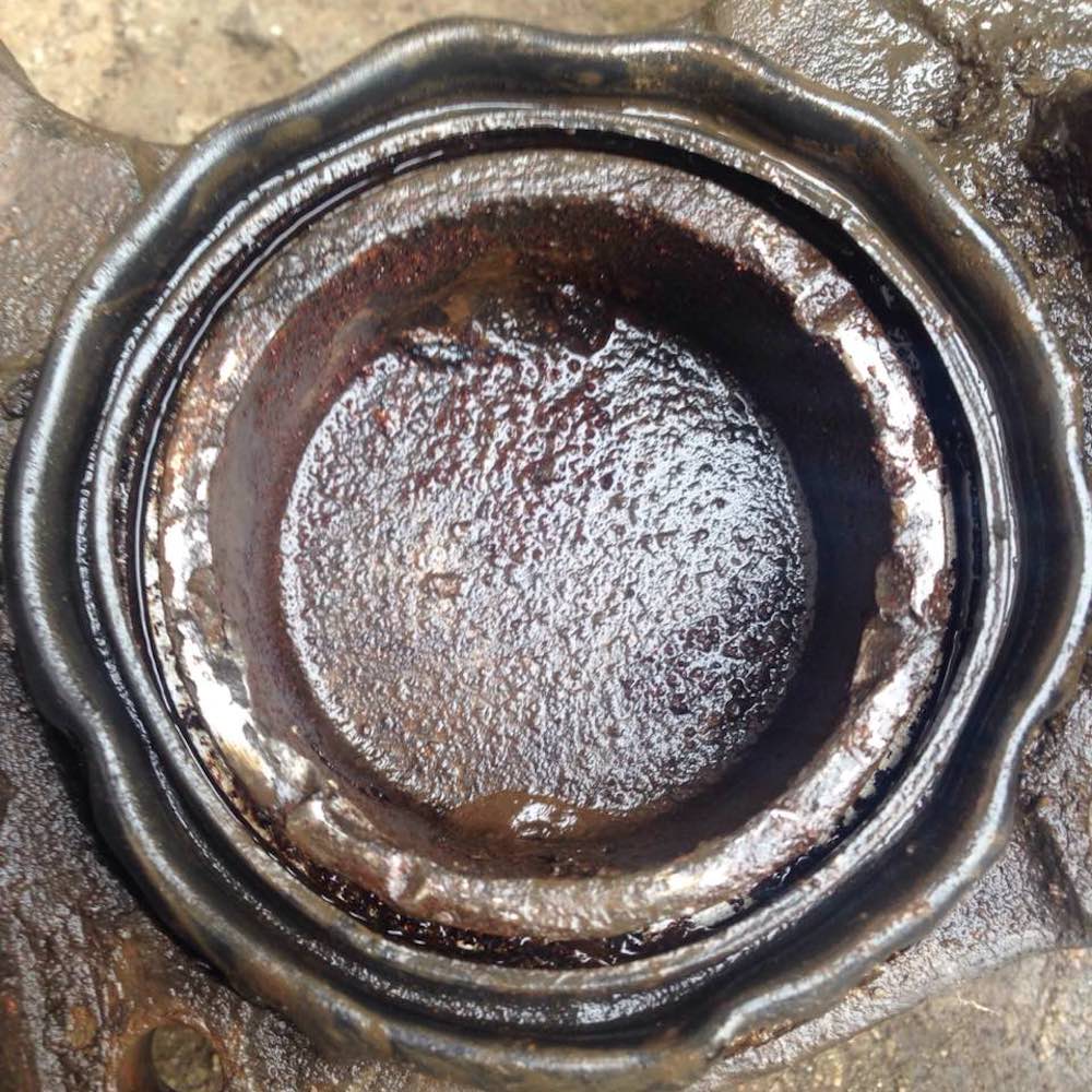
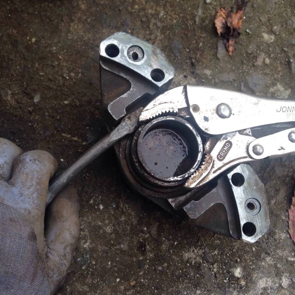


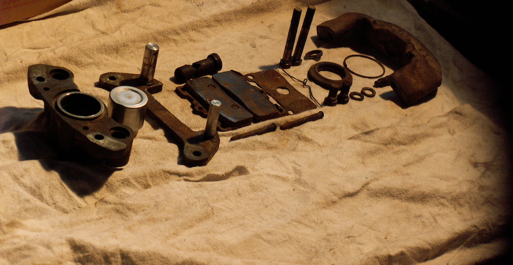

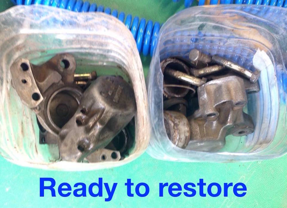
So after 100% disassembling and defect detection the parts of each caliper were placed in a separate box with proper sign.
Part 3. How it works
In general, IMHO, both the front and rear brakes on our cars have a rather interesting and complex design. Rear (in case of independent suspension) disc single-piston, with a caliper on a movable bracket with free movement, with a piston diameter of 43 mm. The bracket has two cylindrical rods, one of which moves in a cylinder with grease, protected by a seal, the other moves in a shock-absorbing rubber insert-cylinder. The movement of the entire caliper along the rods of the bracket, rigidly fixed to the hub bracket, makes it floating. Such movement makes the pressure on both sides of the disc almost uniform (minus friction in two different pairs of the "rod-cylinder" bracket), helps the pads release the disc after braking and compensates for possible uneven wear, and also contributes to the "automatic adjustment" of the pad unit to the disc when installing the caliper.

The front disc brakes are designed on a completely different principle. No floating calipers, seals or rubber cylinders - only two oppositely located pistons with a diameter of 54 mm, squeezing the disc from both sides. Hence, absolutely equal (in serviceable brakes) pressure on both sides of the disc, no possible jamming in the guides and significant (compared to the rear) braking force. In both the rear and front calipers, despite the apparent simplicity of the design, there are quite a large number of parts - about 20 in the rear, about 30 in the front. Both the rear and front calipers use cylindrical guides (pins) for the pads, which the manufacturer later gradually began to abandon, using the fit of the pads in the grooves of the calipers. Although pins, compared to grooves, create minimal friction for moving the pads, they, unfortunately, are poorly protected against corrosion and require lubrication and careful monitoring of their condition during vehicle operation.

Part 4. Search for spare parts
Next, I started looking for parts to replace all the parts that had failed, either partially or completely.
To be honest, this was not an easy task and was complicated by the fact that it was quite difficult to find independent rear suspension in our body in the catalogs and the diagram of the rear disc brakes as well. But even if I managed to find and find out the part number, I was most often refused to supply the necessary part due to the "antiquity" of the model. For every ten requests, there could be nine refusals, and only in one case was I lucky.
The fact is that cars with such a suspension in our body were not supplied to the US market, so the huge auto parts industry of this country could not always help either, although in the end, it was there that most of the parts for both the rear and front calipers were purchased.
I must note that the search process is very exciting, and in the process you become passionate and obsessed with finding the part you need so much. Now you can simply buy complete repair kits for front and rear brakes for x3/x4/x5/x6 - right on this site there are corresponding links to auctions e-Bay or Yahoo. But that time some parts were found only after weeks of searching, sorting through other cars and "entering" the search from other models. Of course, I had a more "rough" option - to buy restored calipers as a set on e-Bay or from other suppliers - then both rear and front calipers were still on sale. But I left this option for the last resort, if there was no other way out. Frankly speaking, I was stopped by the senselessness of moving a pieces of metal in the form of a caliper body across the border - after all, I already had all the calipers. Note that I was never destined to use this option - all the necessary parts were found separately. Be that as it may, the result of my many months of searching, waiting and shopping trips was a whole box of spare parts for brakes and other equipment.
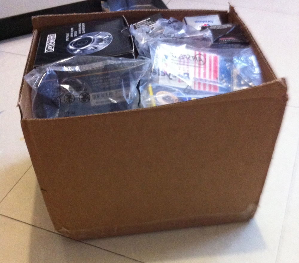
As for the modern caliper repair kits I mentioned above, I'll talk about them below.
Part 5. Restoration process
After some time, I finally got around to the long-awaited restoration of my car's brake system. I started with electrical cleaning, priming and painting the caliper housings.
Here and below I'll use the pictures from my first restoration as well as pictures from another restoration I've done later - the only reason is to complete the tips with adequate illustrations.
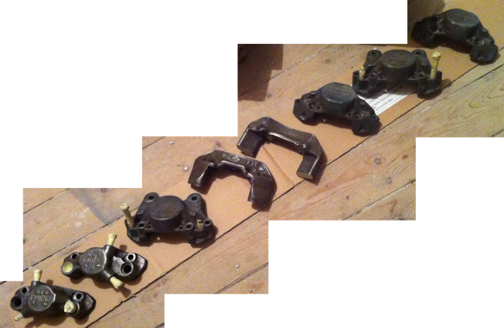
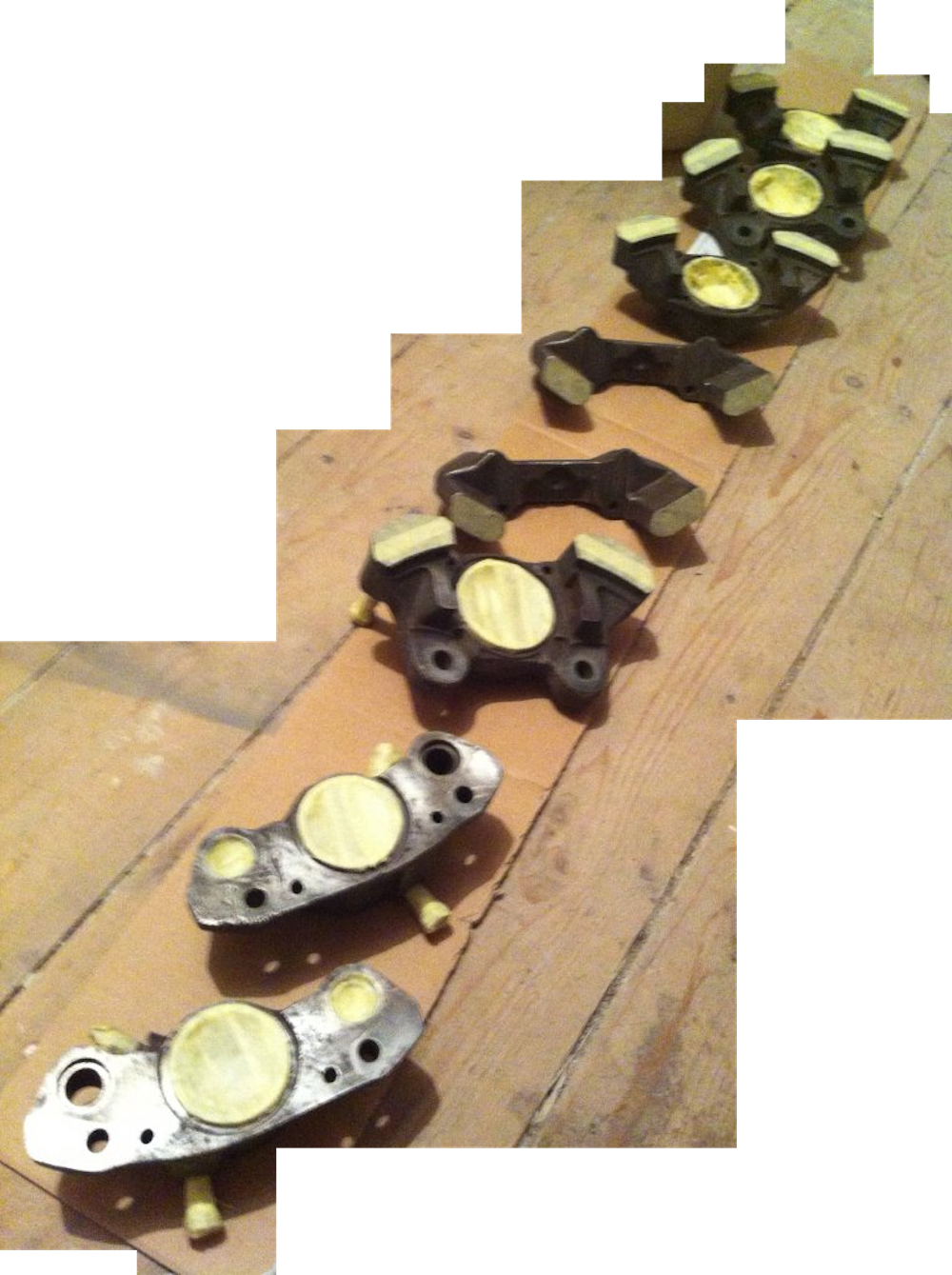
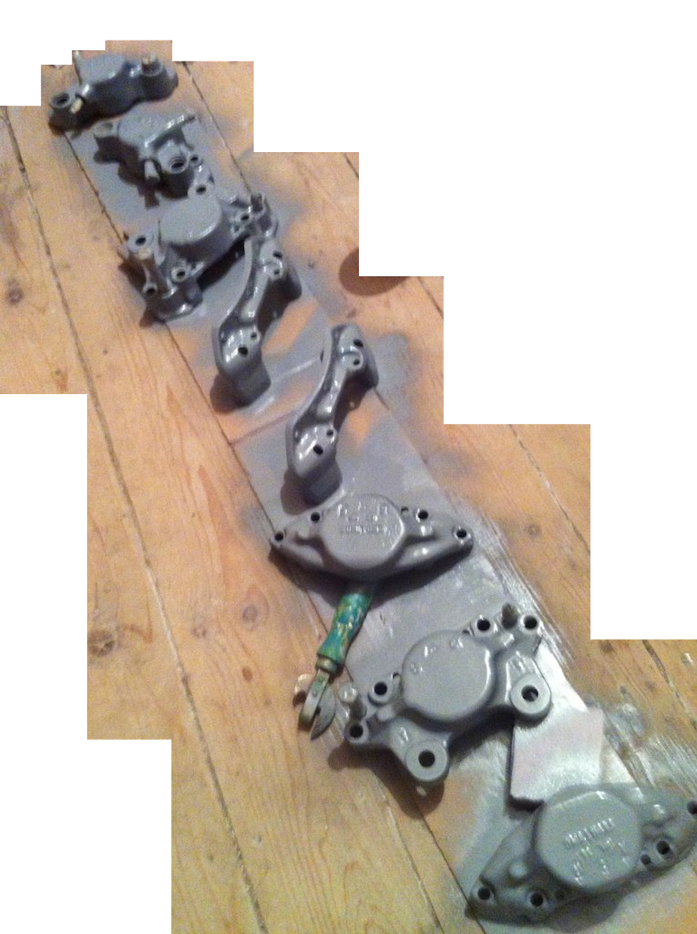
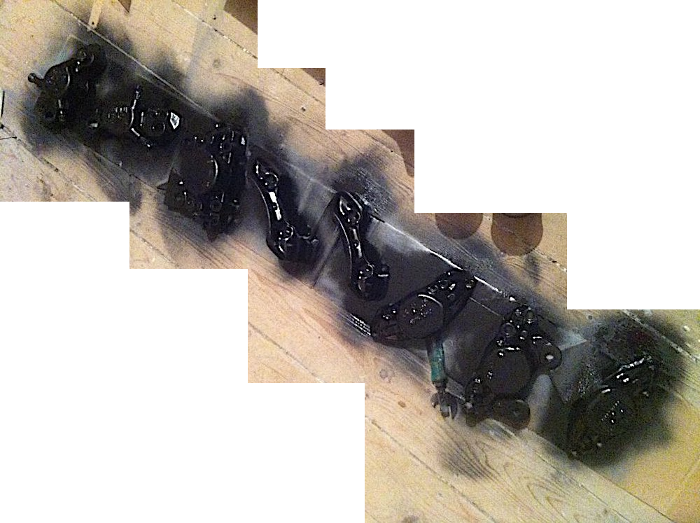
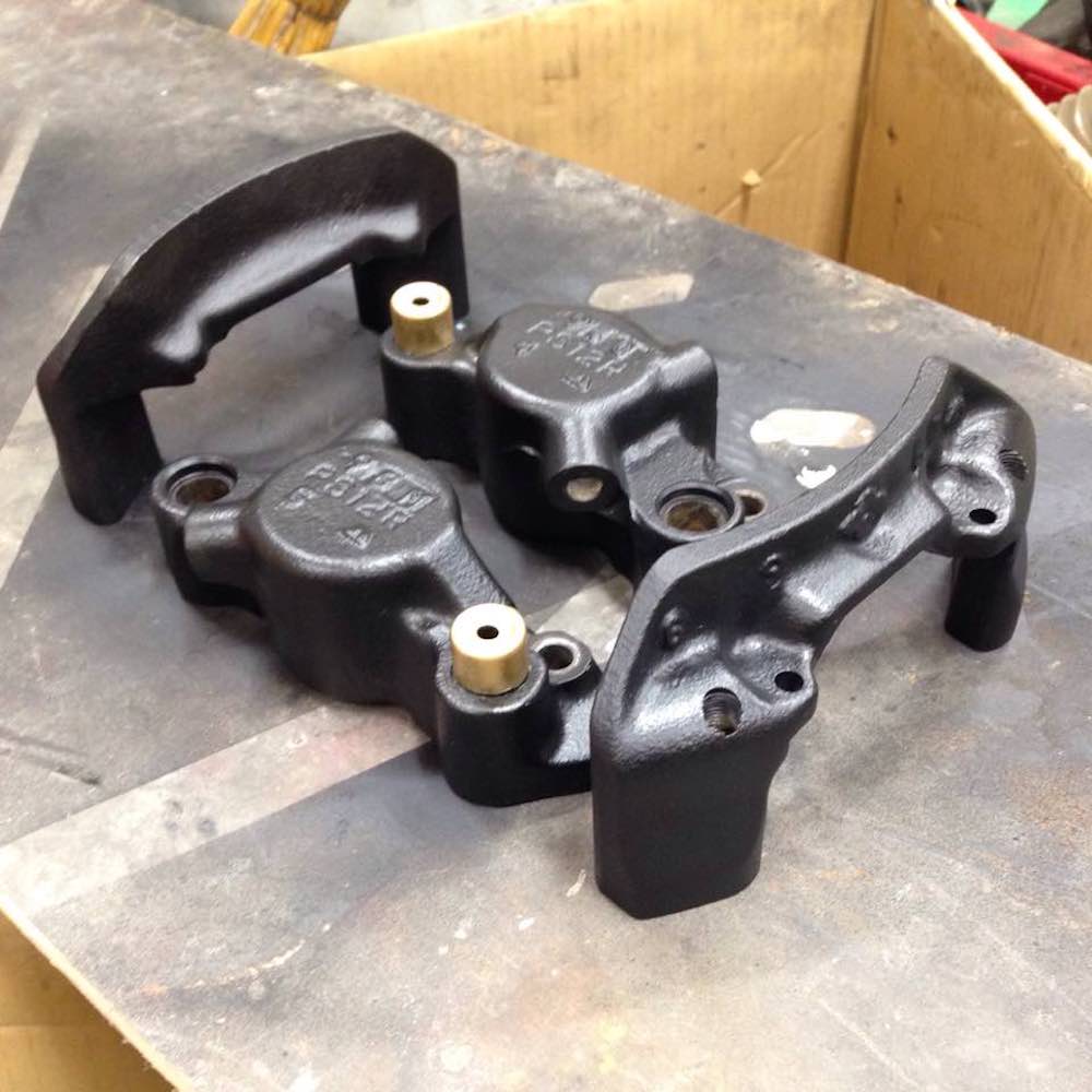
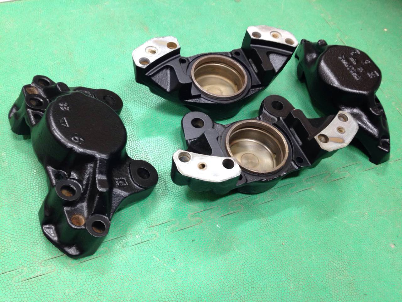
The electrical cleaning of rust from parts using an electrolyte and a power source, which I used here, is described by me separately. Only those parts for which I could not find a replacement were subjected to the cleaning and painting process.
Part 6. Rear caliper assembling
The rear caliper model described below was used on the following 1976-1984 Toyota cars: Mark II, Cressida, Crown, Carina, Corona, Chaser, Cresta, Soarer and others.
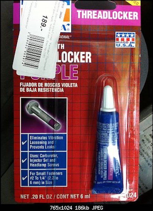
So I started assembling the mechanism itself. To assembly use regular tools - you need a set of heads, a flat screwdriver, pliers, a light hammer, and a clamp. Thread cutting and cleaning tools wouldn't hurt either. During the assembly I used Permatex caliper grease and Permatex thread locker:


Next, I will tell you about assembling the rear caliper.
Important! The caliper bracket is put in place before the parts are fastened with bolts! Assembling in a different order can lead to an error and the need for rework.
Now let me mention the repair kit for the rear caliper of the type in question.
The kit F123441 (or F123442 - for vented discs) includes 26 parts for two rear calipers overhaul as shown on the picture below:
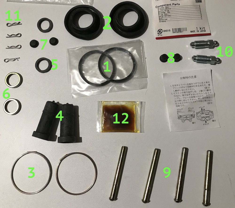
1. piston seal (2 pcs.)
2. piston boot (2 pcs.)
3. piston set ring (2 pcs.)
4. torque plate pin bushing (2 psc.)
5. dust seal (2 pcs.)
6. dust seal retainer (2 pcs.)
7. plug valve (2 pcs.)
8. bleeder cap (2 pcs.)
9. hole pin (4 pcs.)
10. bleeder (2 pcs.)
11. split-pin (4 pcs.)
12. grease (1 pcs.)
Please note that this type of caliper might be initially equipped with one of two type bleeders – 6(7) mm or 9(10) mm thread thickness. In addition, your car might have vented or non-vented rear discs. This makes the difference to some parts included.
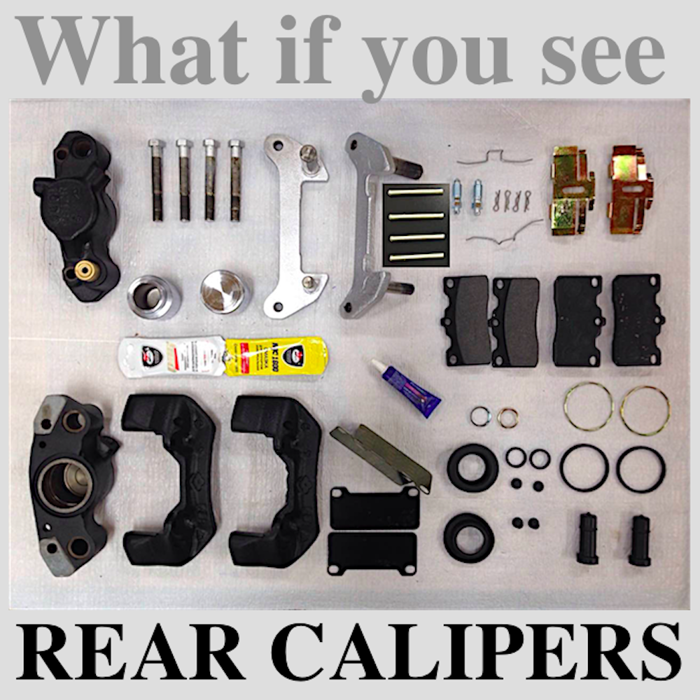
Firstly lay out everything that needs to be replaced: on the right in the photo below are the old parts, on the left are the new ones to replace them.

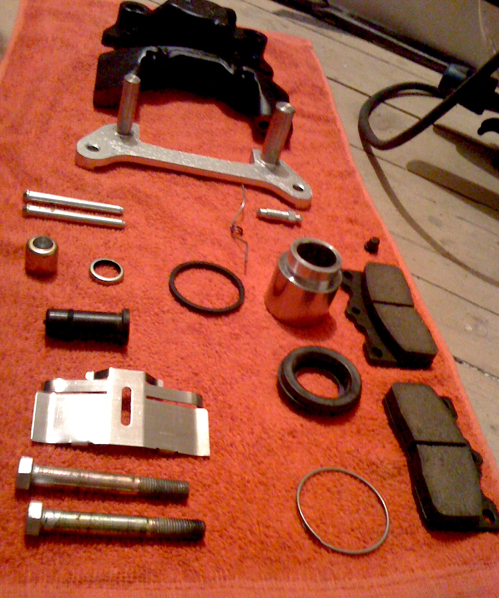
Then lay out all the parts of the caliper intended for assembly as a complete set:
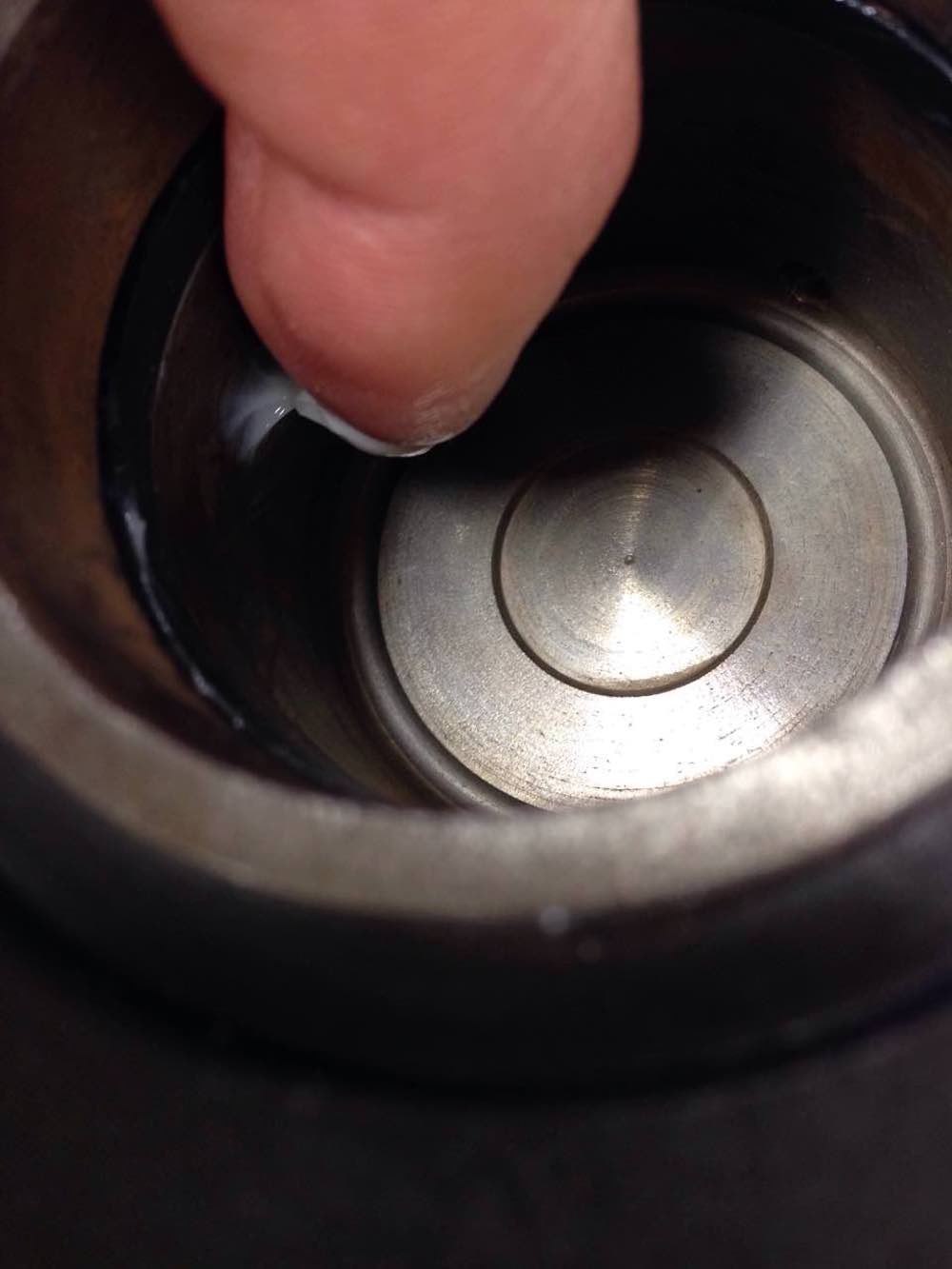
First, insert the lubricated rubber ring into the groove of the cylinder:

Then put the dust cover on the piston...
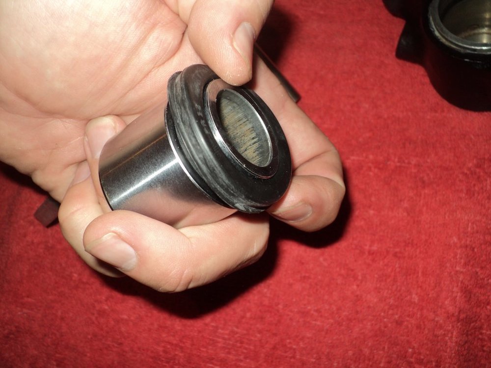
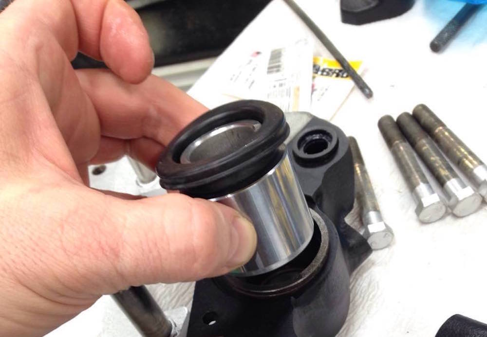
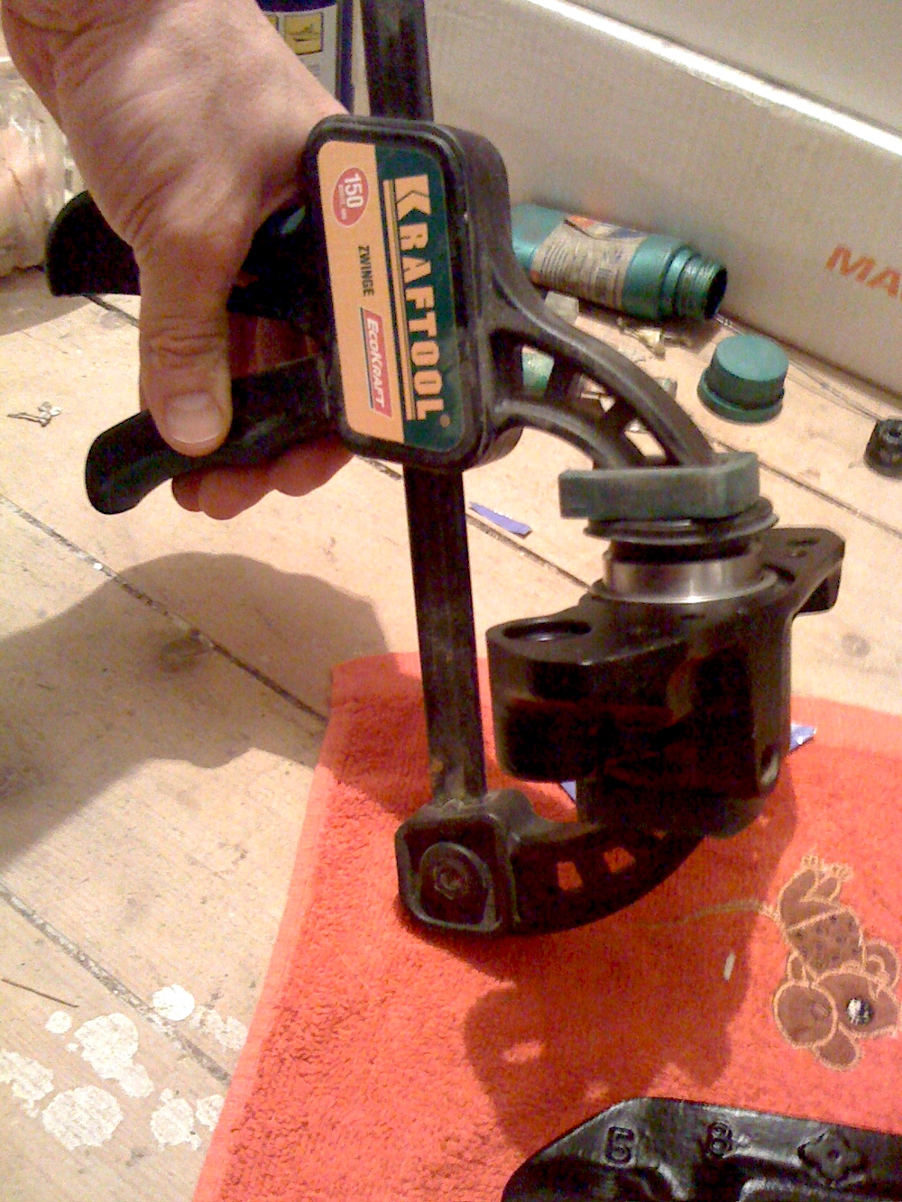
…and carefully insert the piston into the cylinder 5-7 mm deep until it touches the inner rubber ring of the cylinder. Then, using a clamp, gently and without distortions, push the piston into the cylinder until it stops:
Then we calmly put the boot on the outer rim of the cylinder and secure it with a steel ring:
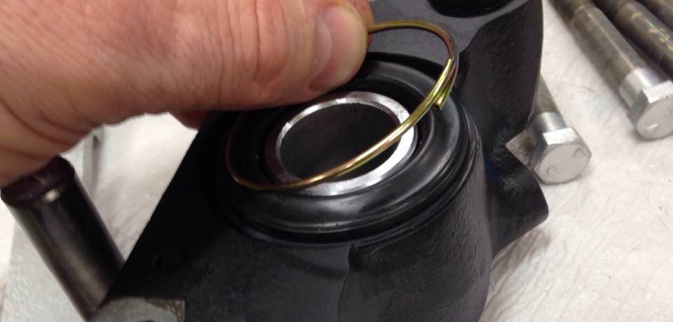
So the piston and the cylinder become married :)

After slightly moistening the rubber insert it into the bracket cylinder:

So that it is flush with the plane of the caliper. And here it is already in place, slightly recessed into the recess of the body:
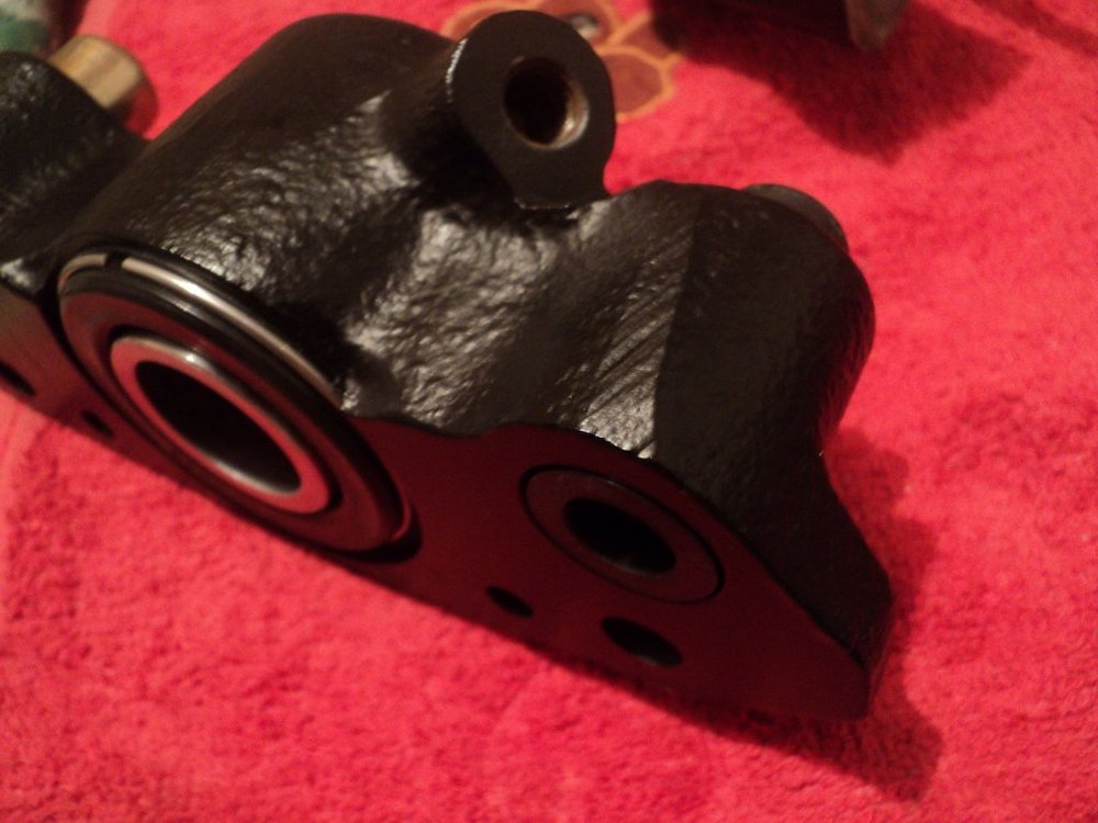
Apply the grease into the small cylinder. Using light hammer blows, press the seal and cap of the second cylinder into place:


Replace small plug valve to the new one:


Having lubricated the housing cylinders and the rods of the bracket, we carefully and without distortions insert it into place:
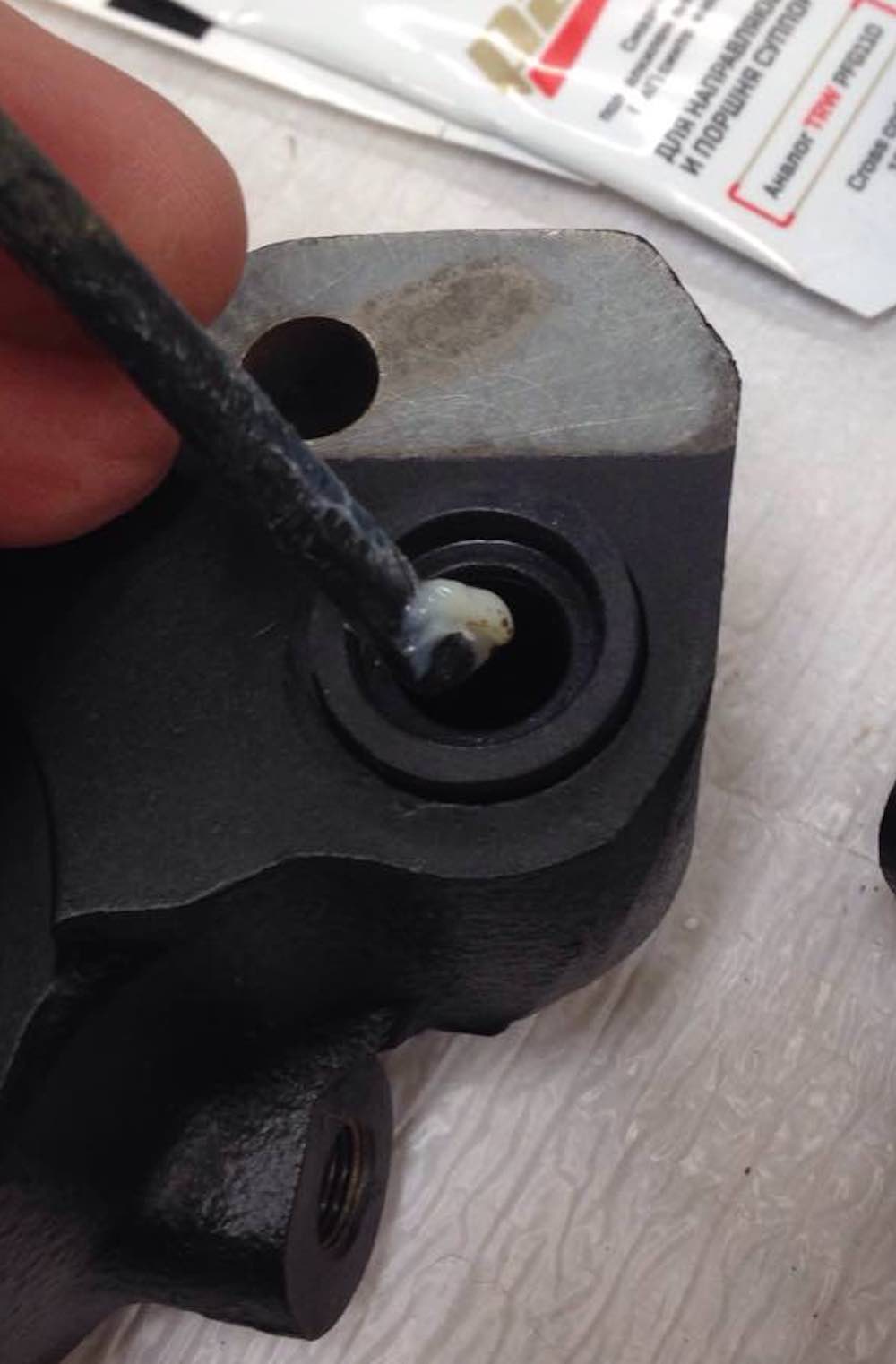
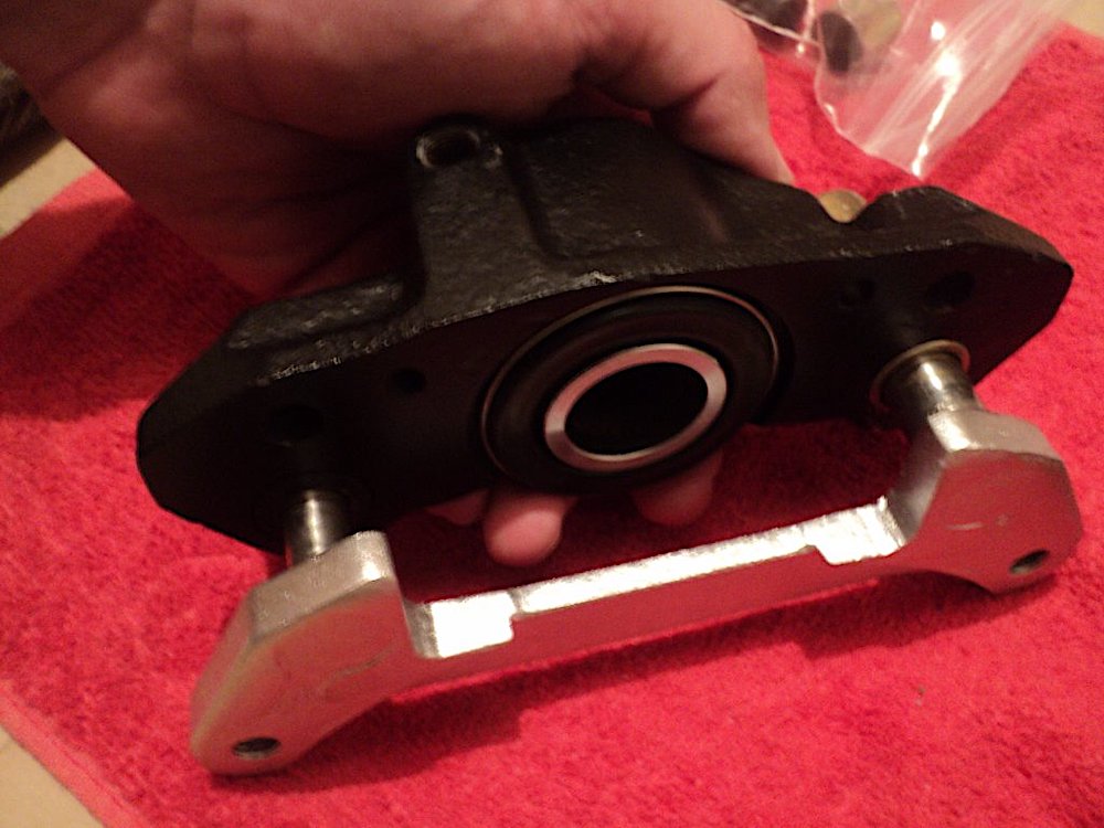
Click HERE for video with proper working of bracket after installation.
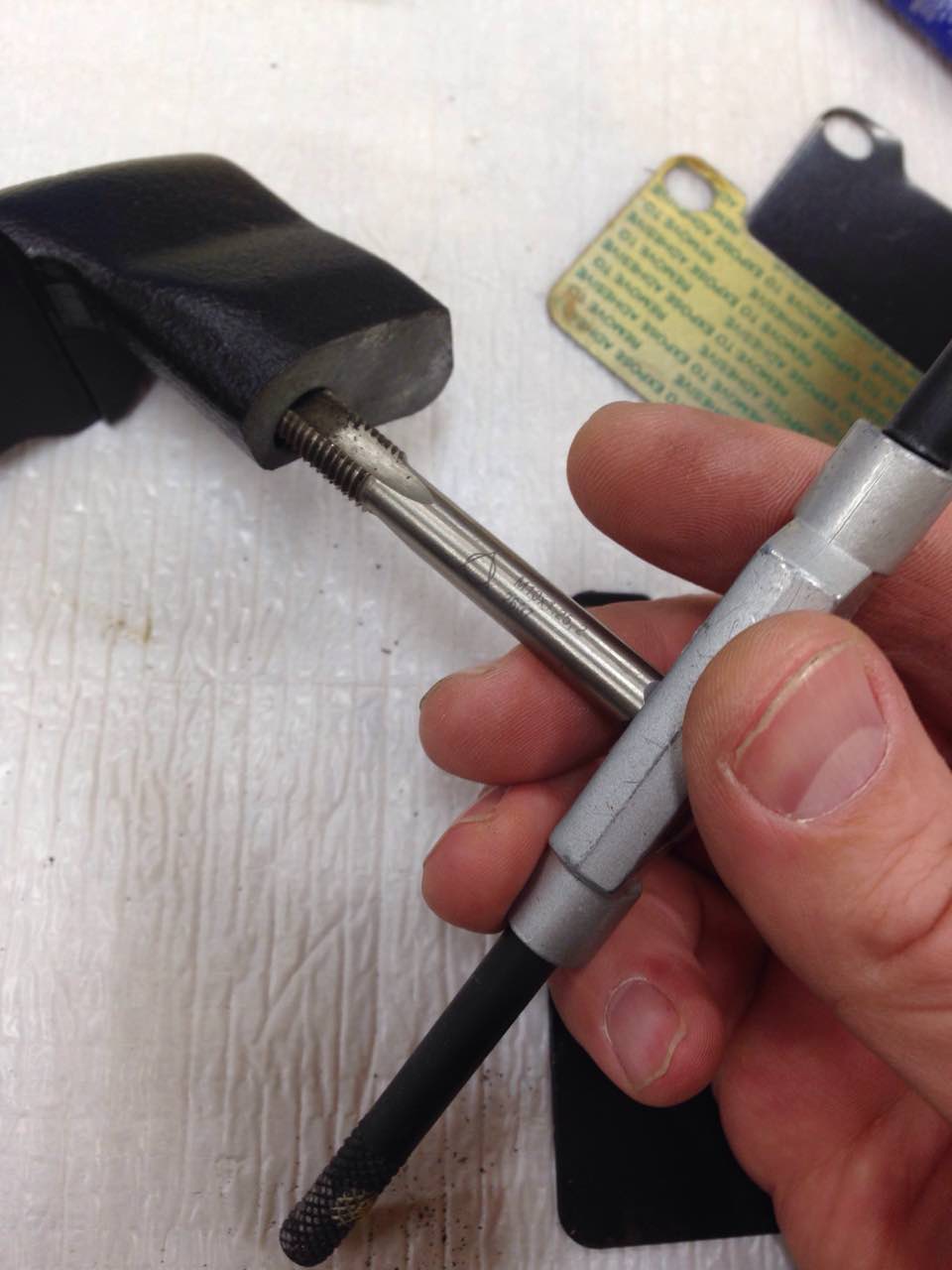
Then we clean the threads on the bolts and the housing:
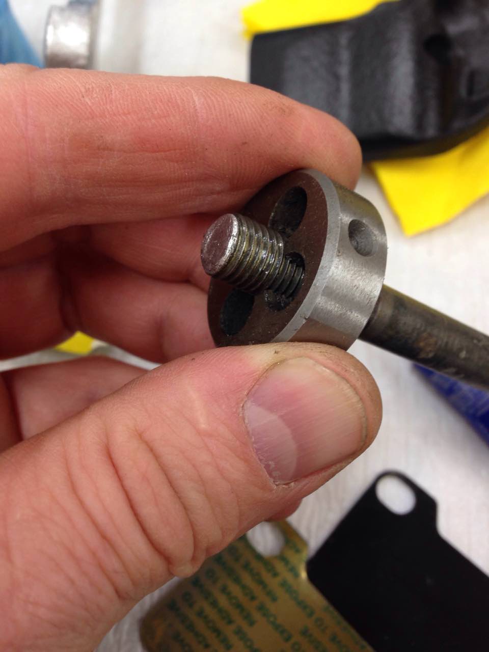
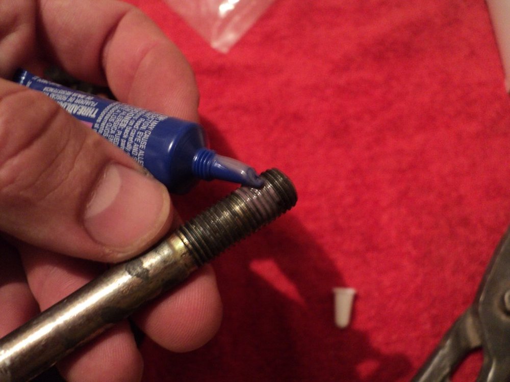
Apply thread sealant to the bolts:
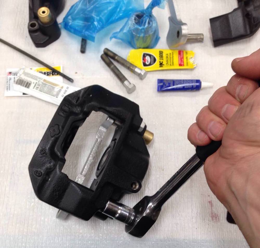
And both parts of the caliper should be tightened with the bolts:
If you are lucky enough to have special self-adhesive noise-absorbing plates then degrease the pads for gluing and remove the film before pressing these two parts together:


Assemble and install the pads unit – pins/springs/pads:
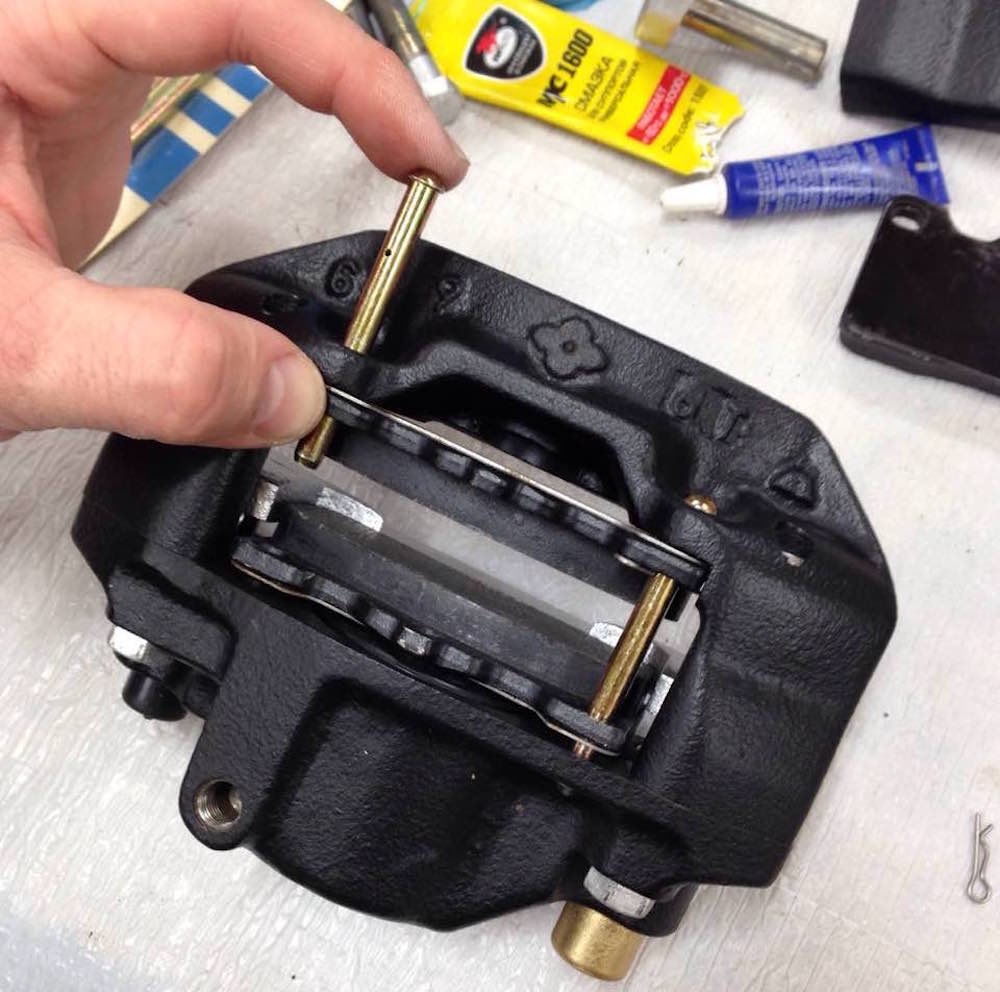
Apply the grease to pins: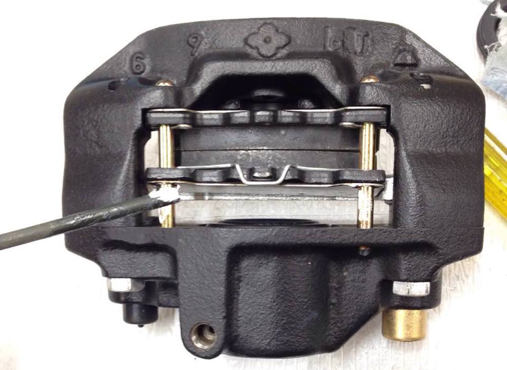
Install the protective plate:
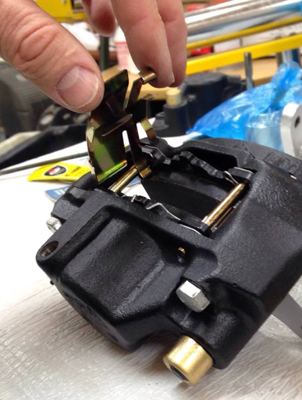
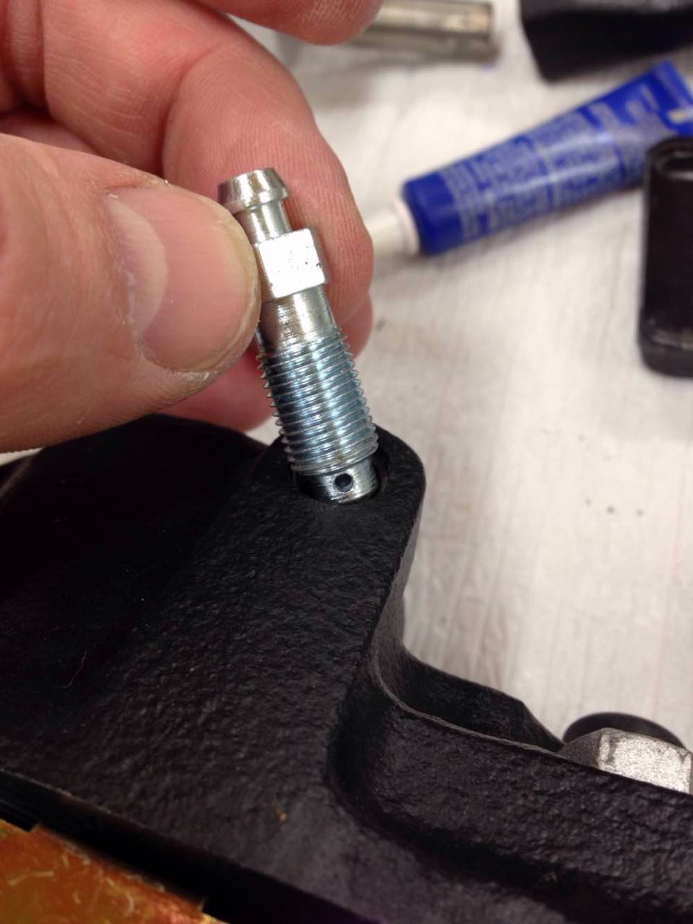
Screw the bleed nipple back into place...
... and "Voila!" - the assembled caliper is in our hands!

Then we “magically” double their number:
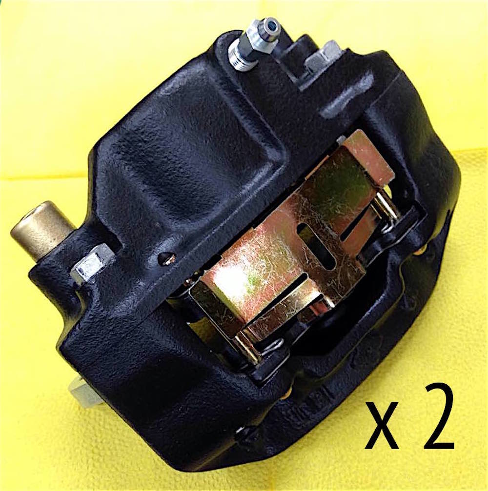
And only then (finally!!!) the rear brake mechanisms take their modest regular place:
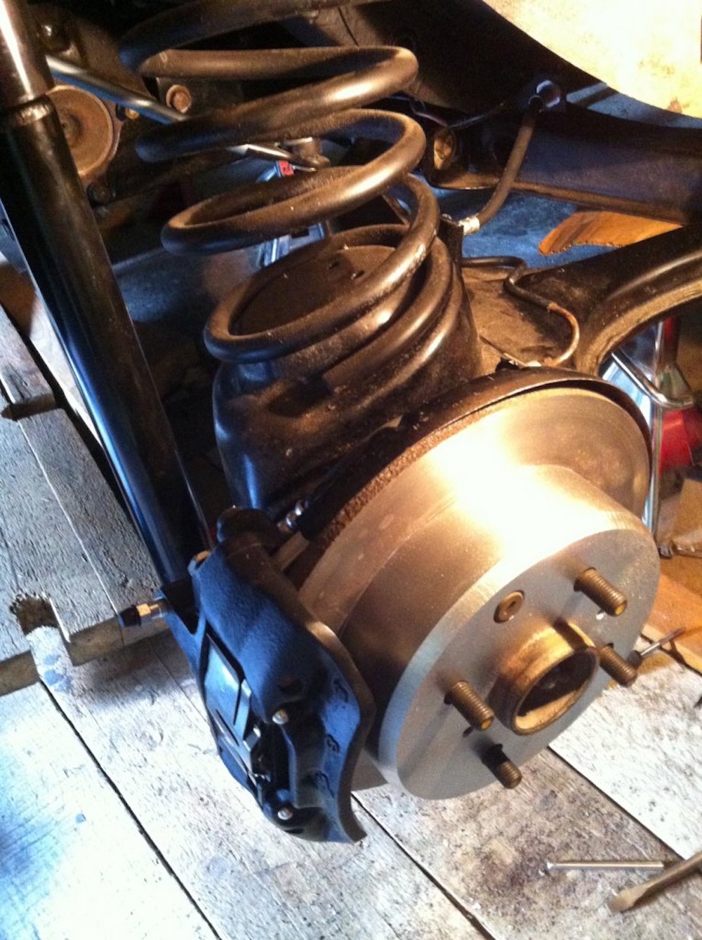
It’s time to take a short break and gather our strength for further work.

Part 7. Front caliper assembling

Here I will tell you the process of assembling the front caliper.
At first a couple of words about the full overhaul caliper kit #E30667.
The kit includes 34 parts for two calipers (4 cylinders) overhaul as shown on the picture below:
1. piston boot (4 pcs.)
2. piston set ring (4 pcs.)
3. piston seal (4 pcs.)
4. split-pin (4 pcs.)
5. pads plate (4 pcs.)
6. pads spring (2 pcs.)
7. hole pin (4 pcs.)
8. fluid channel gasket (4 pcs.)
9. plug (bleeder) (2 pcs.)
10. bleeder cap (2 pcs.)
The parts included allow you to completely overhaul both front calipers at once, replacing almost everything that is old or rusty.
So at first lay out the kit and housings for assembling one caliper:
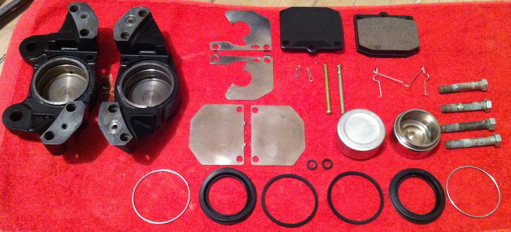
Apply the lubricant to the cylinder sealing ring: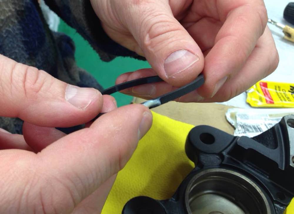
Insert the seal
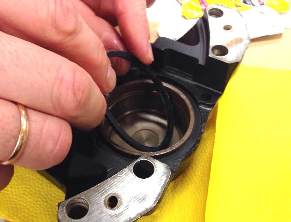
Put the dust cover on the piston:

Lubricate the groove of the cylinder sealing ring:
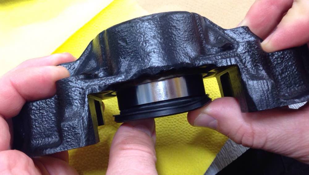
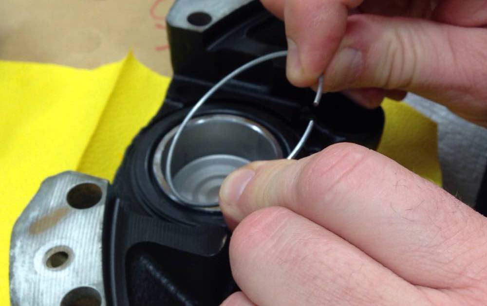
Using a clamp tactfully (or just with strong hands :) mount the pistons and dust boots.
Repeat to obtain two halves:

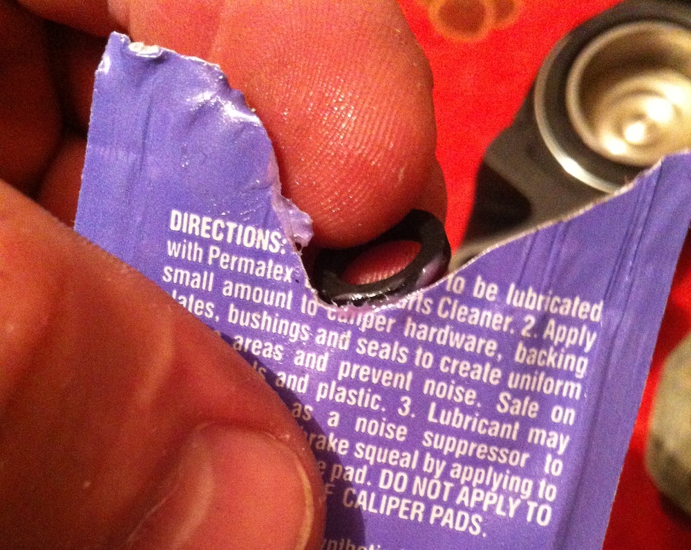
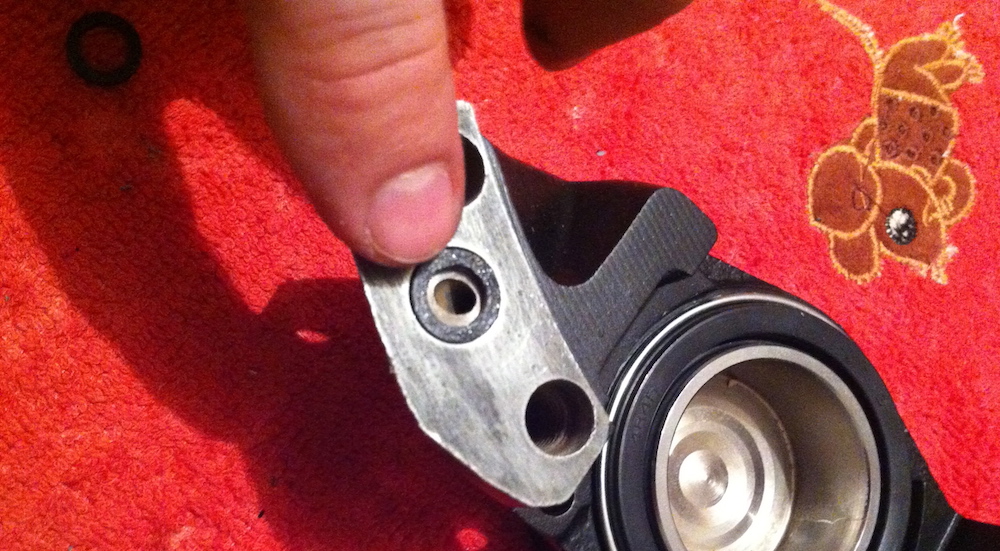
Next, don’t forget to put in place two small rings from the kit connecting the brake fluid flow channels between the cylinders – lubricate them and insert them into the recesses in one of the housing:
Clear the treads, apply the locker to the thread of the four bolts and tighten the right and the left parts of the caliper together:

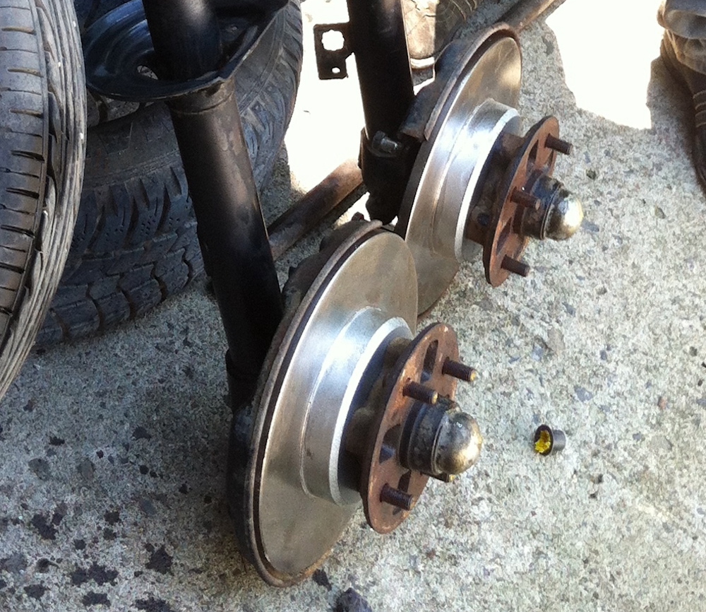
If it necessary, unscrew the bolts on the back side of the hub and replace the brake discs:
The front pads were bought on e-Bay with a corresponding drawing showing the presence of a recess for the pad wear sensor. In fact, the pads arrived without such recesses, although the number on the box :) was corrected. For this reason, we had to mill such recesses ourselves.
Next, insert the sensor into the recess and assemble the shoe unit, not forgetting about the stainless-steel plates.
Important! The arrows on the small anti-squeak plates of both pads should point forward in the direction of the car's movement; the larger plate is adjacent to the shoe, then we apply the small one.

Having placed the pad with the sensor in place, we insert the guide pins halfway up the length and put both shoulders of the spring on one pin.
Then put the second pad with anti-squeak plates in place. Insert the locking cotter pins into the pin holes.
I should note that sometimes cotter pins are included in repair kits for fixing, sometimes "whiskers". I think there is no particular difference (both the original "whisker" and the kit pins are stainless). Insert the ends of the adjustable spring into the central holes of the pads:

Clear the bleeder tread, screw it…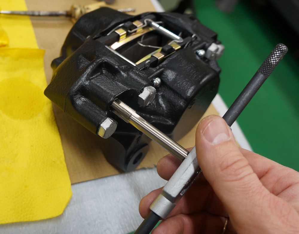
...repeat all over again and the two calipers take the finished look:
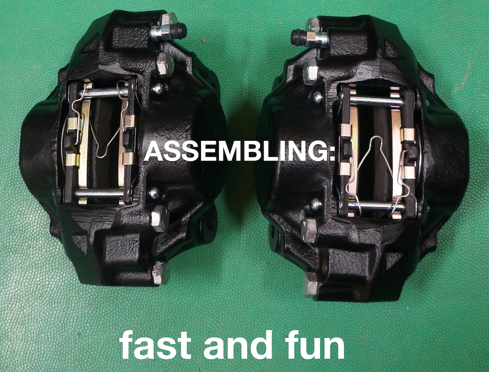
Next, mount the discs and then the calipers in their proper places.
Important! Under the upper front caliper mounting bolt, in addition to the Grover washer, do not forget to put a supporting bracket for the pad wear sensor wire (if it exists on your car specs).
As a result, with joy and satisfaction, you have all the calipers installed in place, ready for filling with working fluid and checking.
2012-2024 by Gonnato